Computer Controlled Machining (WEEK 7 )
‣Make something big( Individual Assignment)
‣Test runout, alignment, speeds, feeds, and toolpaths for your machine (Group Assignment)
About CNC Machine
Computer Numerical Control(CNC) is a method of automating machine using a computer. In manufacturing area this method is used to control machine tools. In our Kochi FABLAB we have a 3- axis CNC Router of SHOPBOT Tools. The bed size is 8 X 4 Feet.
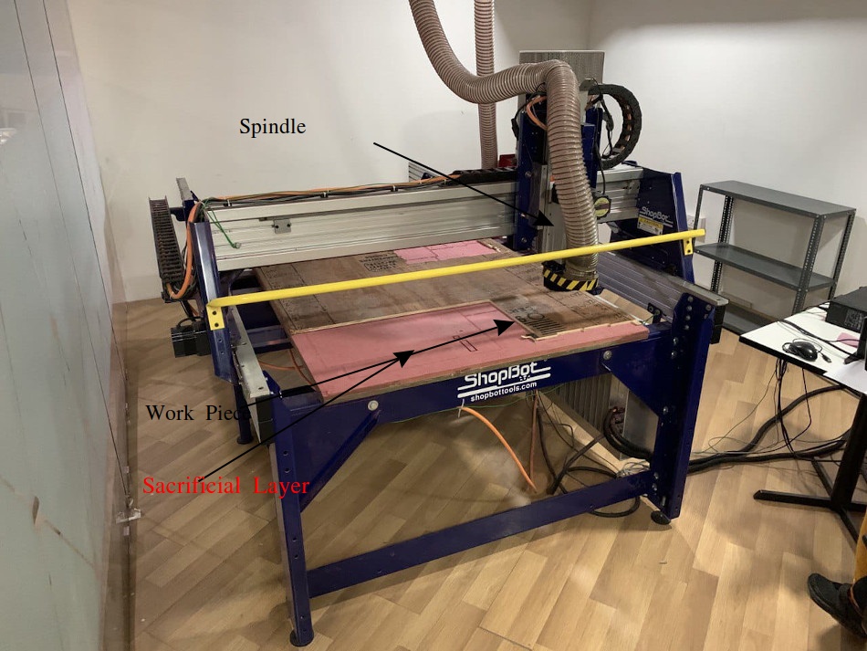
Major Parts/Units of CNC Shopbot
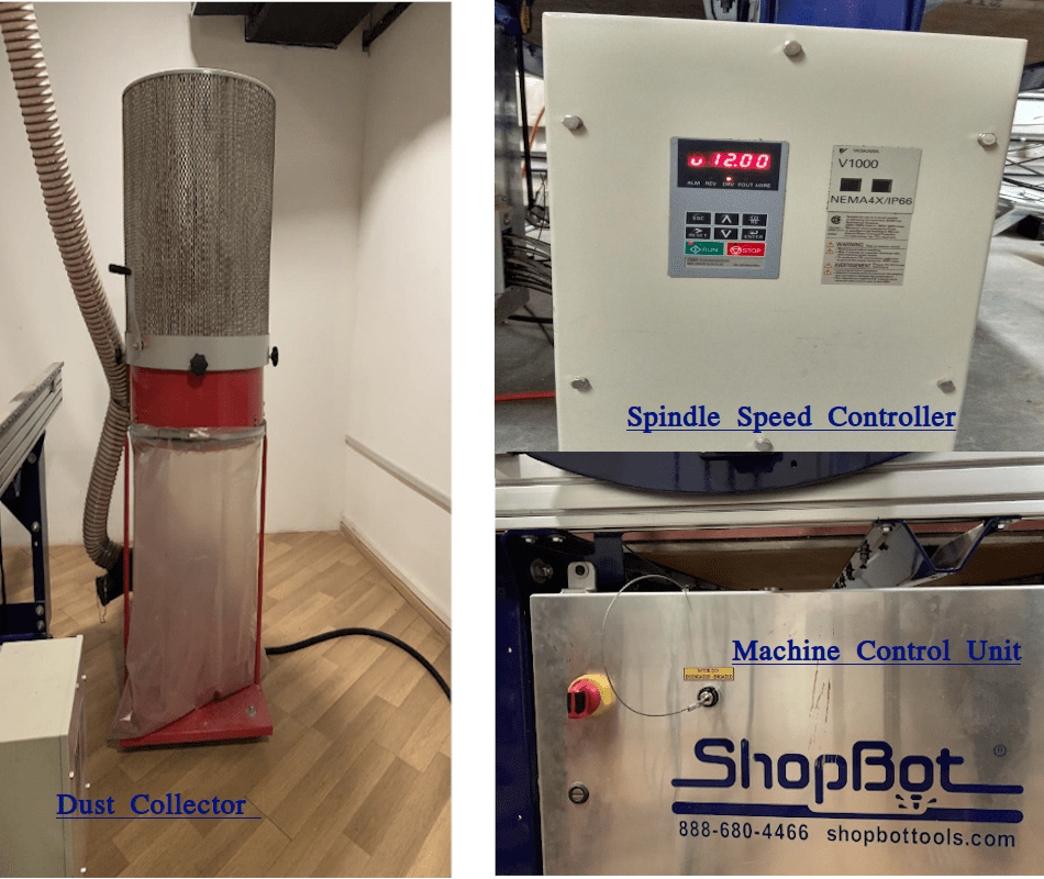
Dust Collector- This unit collects the dust and other debris formed during milling operations. It creates a vacuum and the mouth of this collector is fixed on the spindle.
Spindle Speed Controller- It helps to monitor and controller the rm of spindle Machine Control unit- Its power unit , we can see a key, used to turn on and off the spindle.
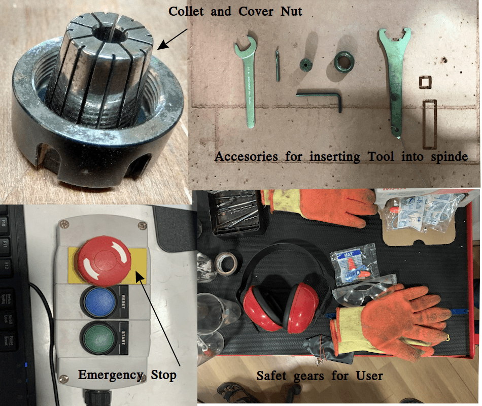
Collect and Cover Nut-Collet is a type of chuck used to hold the tool with spindle. Cover and collect is used together to hold and tighten the tool using a special spanner
Safety Gear- Safety of user is a top priority , Always wear safety gears while operating the machine.
Tool Inserting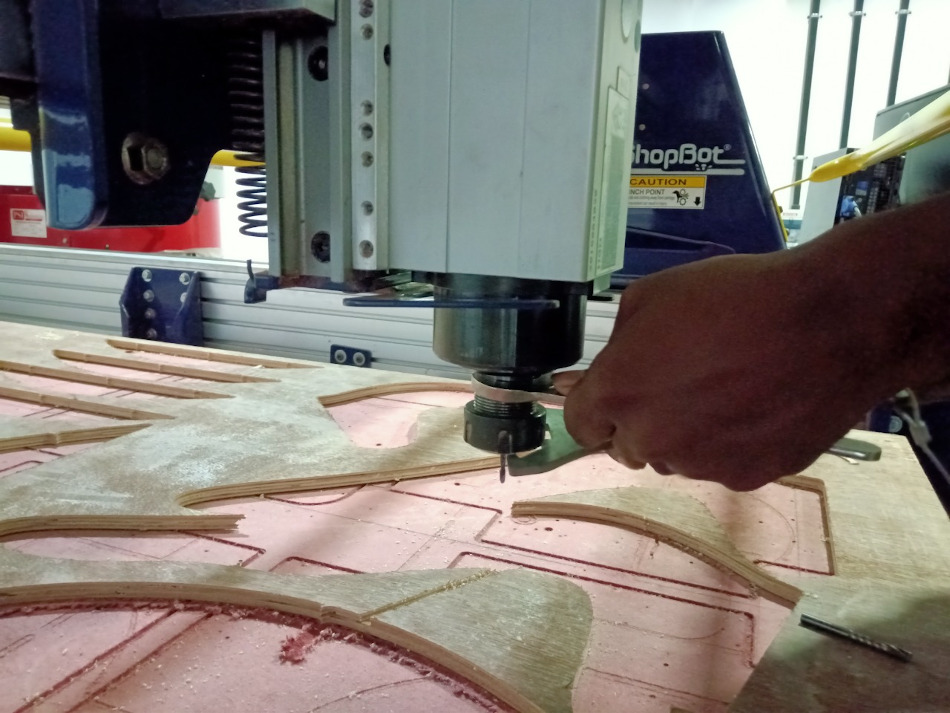 Drill bit Vs End mills
Drill bits are usually used to create cylindrical hole on the materials. Normally bit is moved axially to make holes. End mills are used to cut or remove materials by moving in both axial and lateral directions. milling, profiling, contouring, slotting, counterboring, drilling etc can be done using END mill. Both can differentiated by its geometry , application and manufacturing.
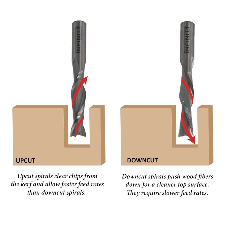
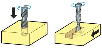 UP CUT and DOWN CUT
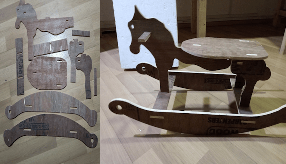
The task was to make something big. I thought of making a ‘ Swing Horse Wooden’ for my baby.
I used FUSION 360 to model my design. The overall dimension is 90 cm X 38 cm X 50 cm. Used parametric designing primarily for setting thickness of plywood sheet, which I set as 18 mm while designing.
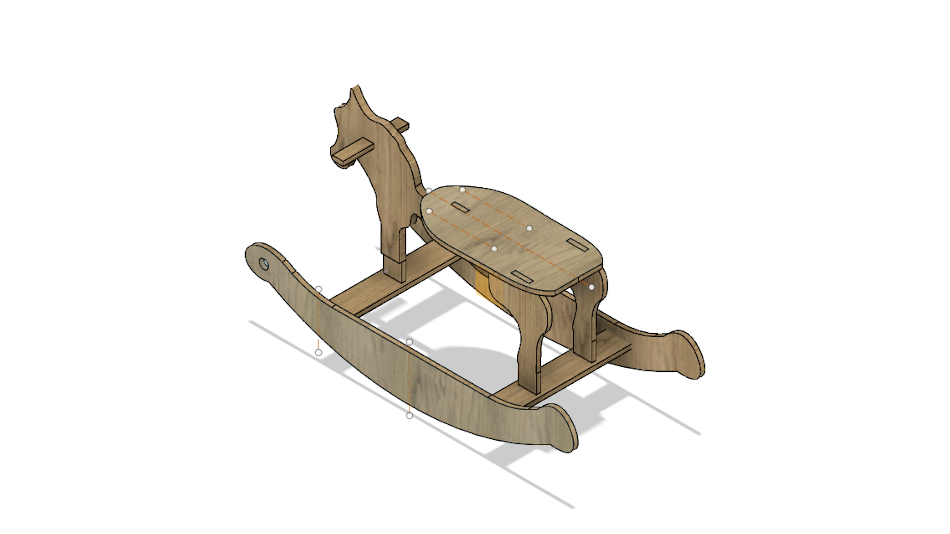
My Design
CNC Shopbot needs a 2D profile(.dxf format) for working. So I projected my 3D design on a plane. I followed this tutorial.
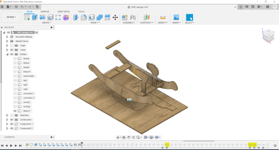
After completing the design, convert all bodies into components
I used the ‘Joint’ and ‘ Move’ operation to arrange all parts/ components on a 2D surface( stock material).
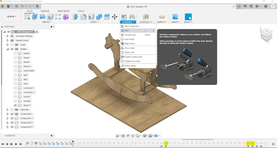
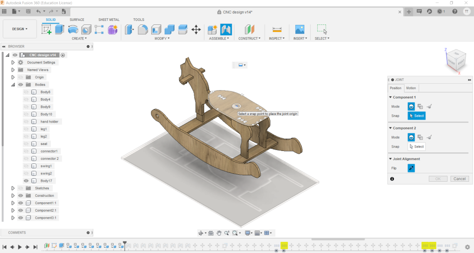
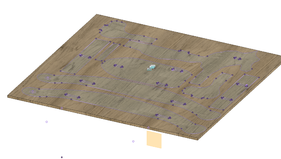
Now using the ‘Projection’ tool create the 2D sketch of all components. Now save the sketch as DXF File.
 Dogbone add in for fusion 360
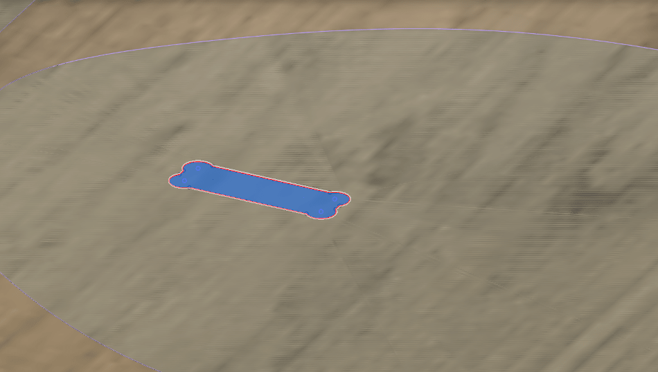
A dog bone design is needed when you have internal cut or pockets while milling.For this, Install the Dog Bone add ins to fusion 360.
I downloaded the file and followed this tutorial for using it.I followed this link for Downloading and Installing
‣ Machine Setting (CNC Shopbot)
Vcarve Pro is a software package offered by Shopbot for machine settings. The DXF file is imported and opened in Vcarve. The steps I followed to generate toolpath are
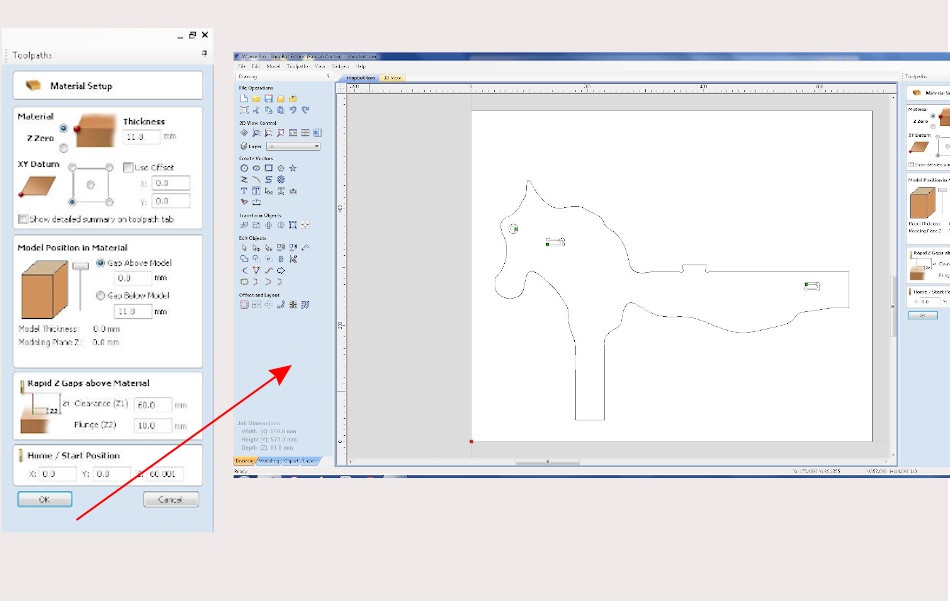
- First step is material setup. Here we want to give Job size ( thickness 11.8 mm), Z zero( where Z axis starts)and datum positions
- Click ‘OK’.
- Drawing page opens, Many tools for drawing and editing will be seen on the left side of the window.
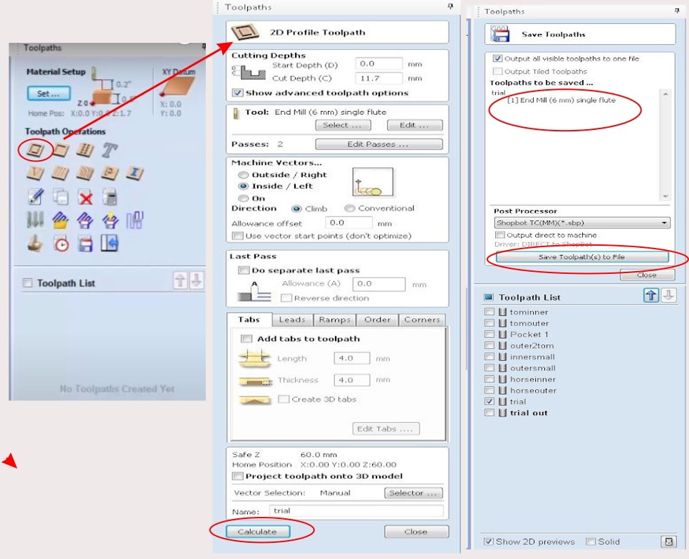
- Click ‘Toolpath operations’ . A side bar will be opened, Here we can give our options.
- For my purpose, I used ‘Pocketing’ to create pockets and ‘ 2D profile toolpath’ for cutting out profiles.
- Select Depth of cut ( 11.7 mm), Machine vectors,Tool Options (End mill 6 mm single flute).
- Select ‘TAB’ this is for holding cutout pieces to the workpiece while milling. Select ‘RAMP’ type.RAMS- define how spindle (tool) plunging into a workpiece
- Finally ‘Calculate’ by giving a filename. Separate files to be created for each toolpath operation.
- Now you can go for preview and check the movement
Steps 1 to 3
Steps 4 to 8
Preview for checking toolpath
.JPG)
Shopbot controlling using Software
Firstly we need to set the ‘home’ position, X- axis, Y - axis and Z - axis of the spindle [priorly, the tool should be inserted into the spindle]. This can be set manually using the keypad buttons available for movement.
Move the tooltip to the required position and set X axis and Y axis to zero. Now we can use an automated method for setting the Z- axis in the shopbot using a zeroing plate
Drill the holes for clamping the workpiece to a sacrificial plate using screws. Make sure the drilled hole would not come in the path of the toolpath. This can be checked during the toolpath file preparation process.
Now Load the file and Activate the machine.
.JPG)
After assembly
Mistake I made
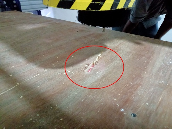
During my first operation to mill pocket the spindle the retraction of the spindle head was small due to misinterpretation of tool length. So the tool plunged into the workpiece and sheared off some material. I rectified the mistake by giving additional clearance.
Link to our group assignment page
Test runout, alignment, speeds, feeds, and toolpaths for your machine
The purpose of this task is to identify the press fit dimension/tolerance required for the stock material, depth of cut, speed etc. In our lab we have 12 mm and 18 mm thickness plywood available for the academy.
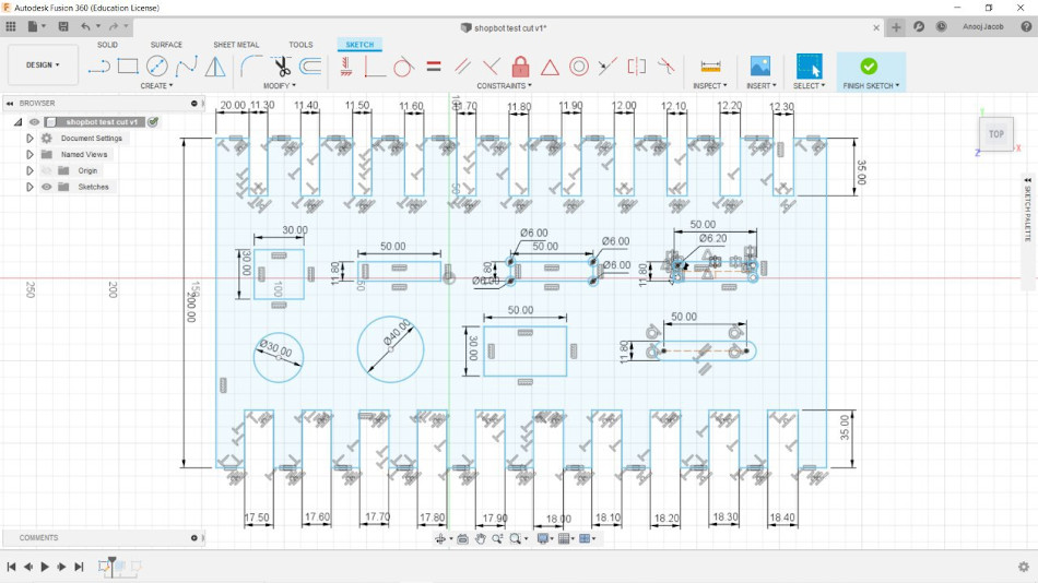
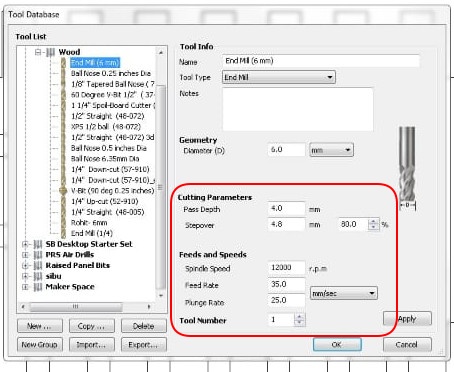
Feed rate, spindle speed settings
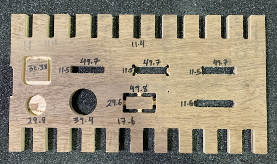
Measured dimensions marked on completed workpiece
 ‣ Remarks
After milling we measured each feature using digital vernier. The design dimensions and dimension measured can be compared from figures.
We got fair test results with small variations of .03 -0.04 % variations. We also understood the dogbone diameter and how the shape of pockets changed.
All the knowledge gained in this helped to complete my individual assignment successfully. I got a good press fit for my workpieces.